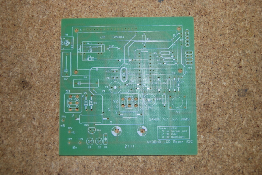
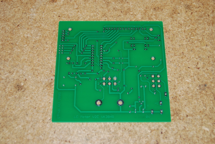
Club L/C Meter Project - Construction Notes and Photos
Construction Notes and
Photographs
Read the G4HUP instructions and these notes before starting
your kit.
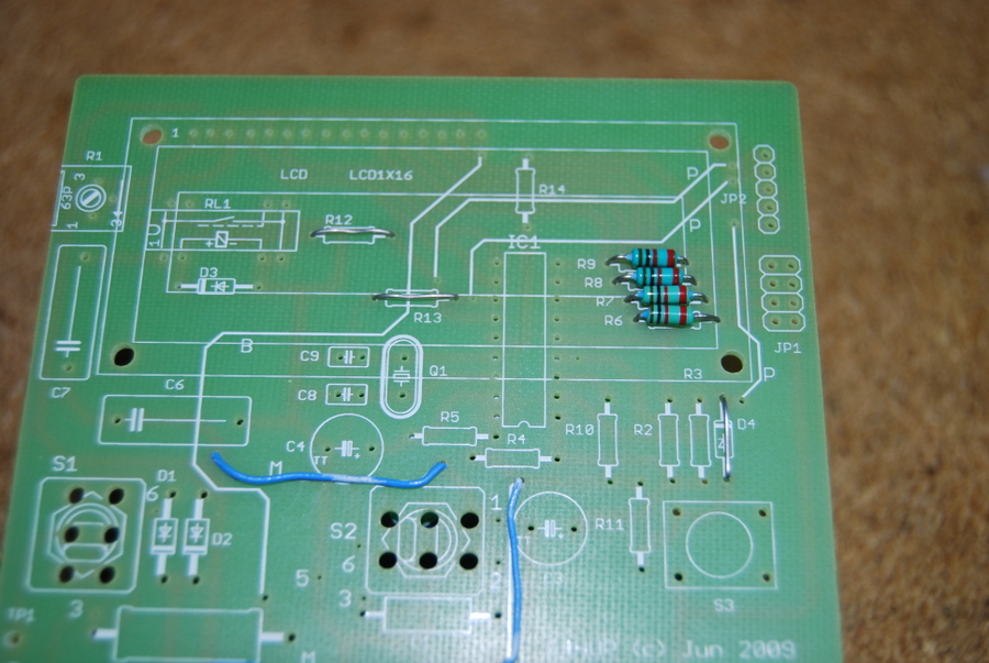
Carefully check and sort the parts, some of the parts have very
similar markings but very different values!
Ensure all the resistors and other parts are flat and neat
against the board with their markings facing in the same
direction - ideally reading left to right. This makes the values
easier to check afterwards. The JP2 - Programming header is
omitted.
No components are included in the kit for a backlight. LCD's
have provision for backlight, so it could be fitted with extra
parts.
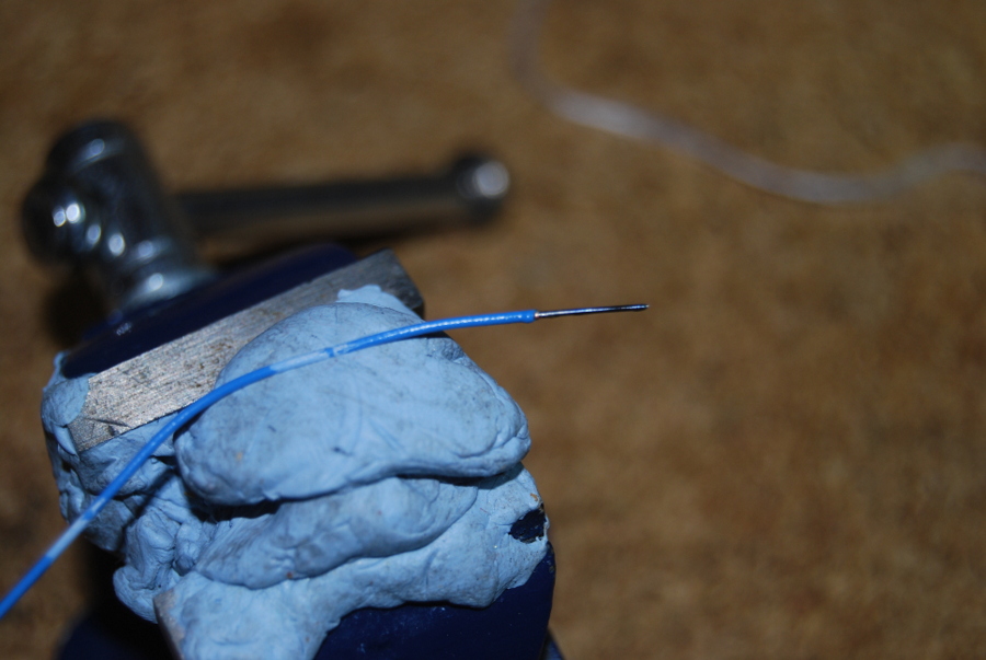
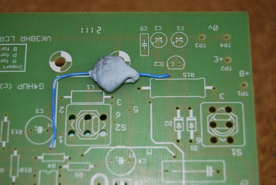
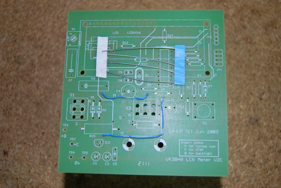
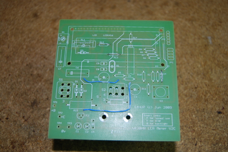
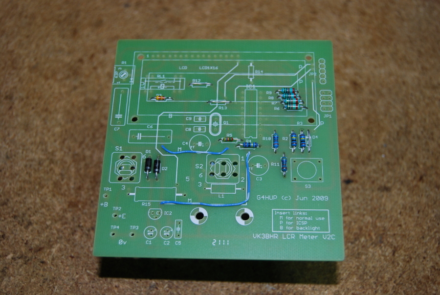
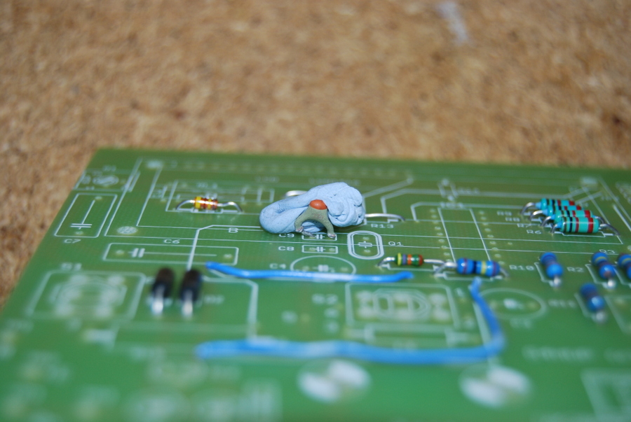
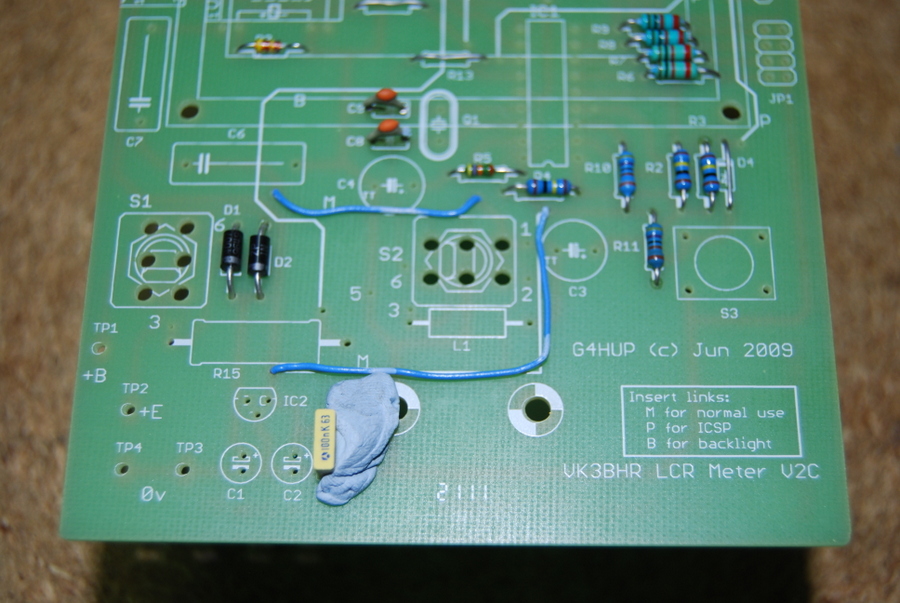
R12,13 shorted for Meter operation, using link wires.
Install the M links for Meter operation using the supplied
hookup wire.
33pf ceramics for the oscillator. You may need to carefully
reform the leads so they fit nicely on the board.
10uf caps longer lead is positive, shorter lead negative.
The + symbol on 10uf tantalum bead caps is very small - check
carefully. You may need to carefully reform the leads so they
fit nicely on the board. It may also be necessary to bend them
flat to the board before soldering to reduce the height.
Depending on height it might be an idea to mount the LCD
display trimmer on its side.
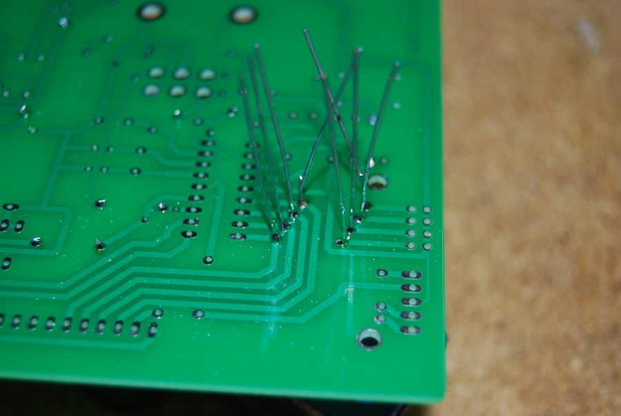
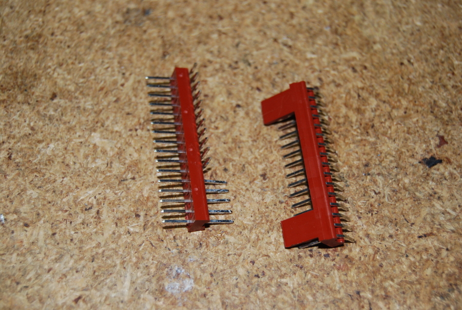
Install the PIN headers for JP1 and single pins at TP 4
(Ground) , 3 (+9 Volts Unswitched) and TP2 (+9 Volts Switched).
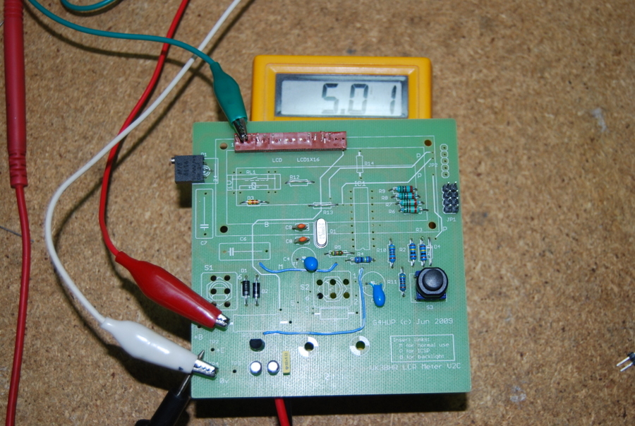
After installing the passive components, install the regulator
and triple check the installed components, then connect up 9
Volts to the TP4 (Ground) an 3 (+9 Volts Unswitched). Check you
have 5 Volts at pin 2 on the LCD and pin 14 (5th pin down on the
right) where the PIC will be. This check should stop your PIC or
display from getting damaged if the 5 Volt regulation circuitry
is not working correctly!
Install the PIC - NOTE points downwards, be very careful to
check the cutout to ensure you have the PIC the right way round
before you solder it in!
Install the Relay chip, check orientation carefully.
Spacers (to be supplied) will be needed before the LCD can be
mounted.
Switches, the inductor (L1) and capacitors (C6,C7) for the
oscillator are to be supplied.
Case options are being investigated.
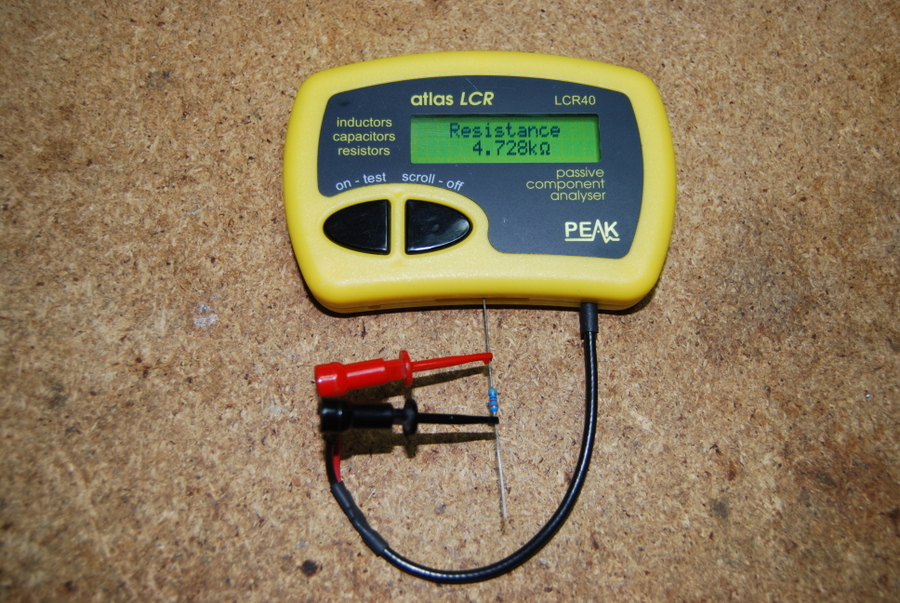
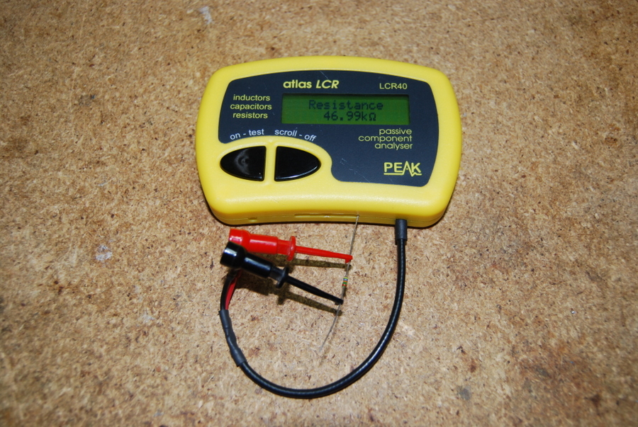
Measured the LCD bias voltage as 335 mV, useful to know for future reference.
Terminals are soldered on last after fitting into the case. This may or may not be an issue depending on the builders case.
Extra washers and longer bolts are available if the LCD
display does not clear the board.
I have sourced some splendid 1% 1nf/1000pf caps, they are big
and green and marked 10000n0 - but are the correct value and
price! They are for C6 and C7.
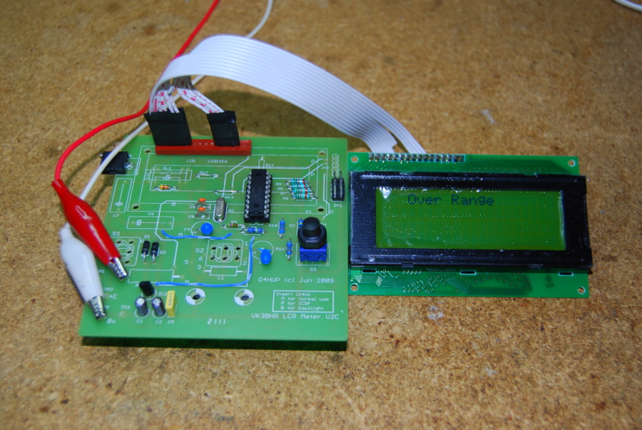
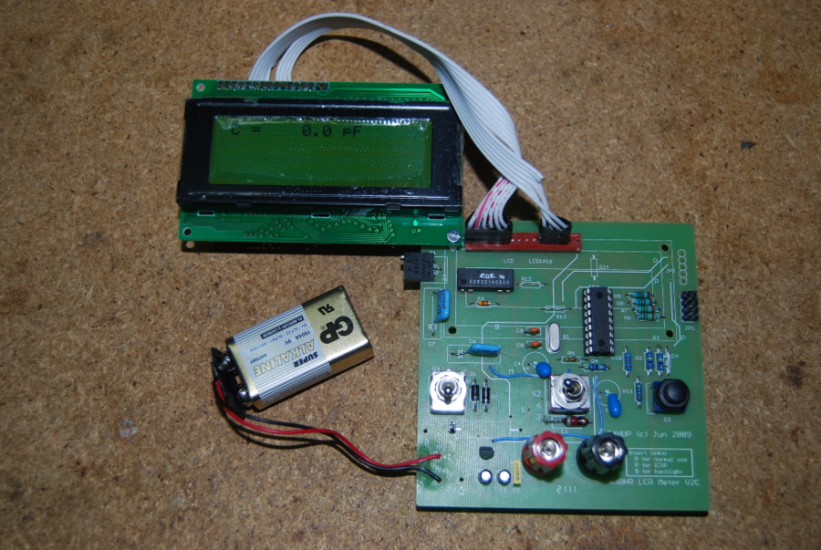
Photographs
The following photographs are
for additional info and guidence only, stick with the G4HUP
manual and the above notes for construction! Also note that I
used a ribbon cable to connect the LCD, your LCD is mounted
later directly above the board.